Each card shows the matching detail image, source drawing, site image, or guide sketch directly in the correct section. Treat every image as a learning reference only, then verify the live project against consented project details, engineer drawings, manufacturer instructions, Auckland Council records, and current NZ requirements.
29 visual guidesImages shown in-place
Foundations
Strip footing
Shows a continuous concrete footing under loadbearing walls.
Strip footing
Guide sketch
Image / reference: Guide sketch — verify against consented structural drawings. Treat this as a learning reference and verify the live project against the consented drawings, specification, manufacturer detail, and current NZ requirements.
This card now shows a simplified strip-footing sketch in the correct footing card. It is deliberately not dimensioned because the actual footing size, reinforcement, cover and bearing requirements must come from the consented structural drawings or engineer.
Technical parts to learn
Excavation: Learn the term, then confirm exact shape, size, product, laps, clearances, fixings, or tolerances from the project detail.
Bearing ground: Learn the term, then confirm exact shape, size, product, laps, clearances, fixings, or tolerances from the project detail.
Reinforcing: Learn the term, then confirm exact shape, size, product, laps, clearances, fixings, or tolerances from the project detail.
Concrete: Learn the term, then confirm exact shape, size, product, laps, clearances, fixings, or tolerances from the project detail.
Starter bars: Learn the term, then confirm exact shape, size, product, laps, clearances, fixings, or tolerances from the project detail.
DPM/interface: Learn the term, then confirm exact shape, size, product, laps, clearances, fixings, or tolerances from the project detail.
Not proven by this image
Project footing width/depth
Bearing ground approval
Bar size/grade/laps
Concrete cover
Inspection approval
Hidden dimensions, laps, clearances, fixings, cover, tolerances, and product-specific requirements must be checked in the consented drawings, engineer details, manufacturer instructions, and inspection records.
What the CM checks
Check footing location and ground
Check reinforcing before pour
Check inspection hold point
Common defects
Wrong width/depth
Soft base
Reinforcing unsupported
How to use this image
The photo annotations now describe visible image features only. Replace with the actual consented detail, engineer detail, manufacturer detail, or a marked-up site photo before using on a live project.
Use where the project is within NZS 3604 scope; always confirm against the consented structural drawings and engineer details.
Consented drawings and specifications
The issued consent drawings, stamped specifications, engineering drawings, RFIs, minor variations, and amendments control the specific project.
Insufficient data to verify
Insufficient data to verify — check the consented drawings, project specification, relevant NZ Standard, or council requirement.
Foundations
Ribraft slab
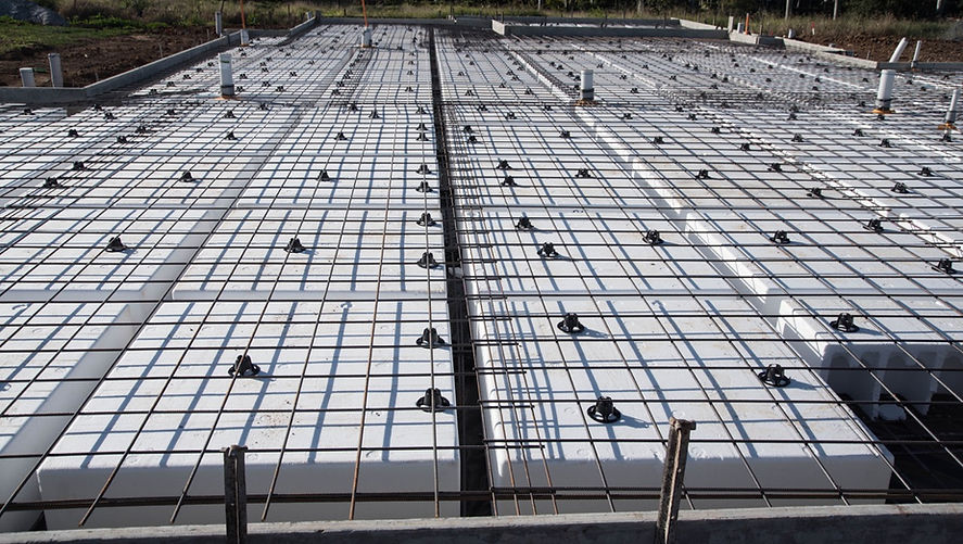
Shows a proprietary raft-style slab with ribs/pods where specified.
Ribraft slab
Reference image
Image / reference: EPS Foam Tauranga / Ribraft pod slab. Treat this as a learning reference and verify the live project against the consented drawings, specification, manufacturer detail, and current NZ requirements.
This image shows a pod/raft-style slab preparation with EPS pods, reinforcement mesh and spacers before concrete placement. Use it to recognise the system on site, then verify the exact proprietary layout and engineering from the consented/manufacturer documents.
Technical parts to learn
Edge beam: Learn the term, then confirm exact shape, size, product, laps, clearances, fixings, or tolerances from the project detail.
Internal ribs: Learn the term, then confirm exact shape, size, product, laps, clearances, fixings, or tolerances from the project detail.
Pods: Learn the term, then confirm exact shape, size, product, laps, clearances, fixings, or tolerances from the project detail.
Reinforcing mesh: Learn the term, then confirm exact shape, size, product, laps, clearances, fixings, or tolerances from the project detail.
DPM: Learn the term, then confirm exact shape, size, product, laps, clearances, fixings, or tolerances from the project detail.
Service penetrations: Learn the term, then confirm exact shape, size, product, laps, clearances, fixings, or tolerances from the project detail.
Not proven by this image
Exact pod layout
Rib dimensions
Edge beam detail
Mesh/bar schedule
Manufacturer inspection requirements
Hidden dimensions, laps, clearances, fixings, cover, tolerances, and product-specific requirements must be checked in the consented drawings, engineer details, manufacturer instructions, and inspection records.
What the CM checks
Use proprietary system manual
Confirm engineer/consent detail
Photograph before pour
Common defects
Wrong pod layout
DPM punctures
Services in wrong place
How to use this image
The photo annotations now describe visible image features only. Replace with the actual consented detail, engineer detail, manufacturer detail, or a marked-up site photo before using on a live project.
Use the exact current installation manual, warranty requirements, BRANZ/Appraisal information where applicable, and product data sheet for the product on site.
Consented drawings and specifications
The issued consent drawings, stamped specifications, engineering drawings, RFIs, minor variations, and amendments control the specific project.
Insufficient data to verify
Insufficient data to verify — check the consented drawings, project specification, relevant NZ Standard, or council requirement.
Foundations
Concrete slab-on-ground
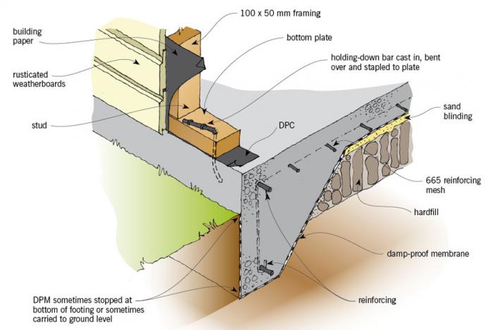
Shows slab layers, sub-base, DPM, reinforcing, edge details, and penetrations.
Concrete slab-on-ground
Reference image
Image / reference: QPOD / Conventional slab illustration. Treat this as a learning reference and verify the live project against the consented drawings, specification, manufacturer detail, and current NZ requirements.
This source illustration is placed in the concrete slab-on-ground card because it shows the slab, DPM, hardfill, mesh, bottom plate and wall/slab relationship. It is a recognition aid, not the controlling project detail.
Technical parts to learn
Subgrade: Learn the term, then confirm exact shape, size, product, laps, clearances, fixings, or tolerances from the project detail.
Basecourse: Learn the term, then confirm exact shape, size, product, laps, clearances, fixings, or tolerances from the project detail.
DPM: Learn the term, then confirm exact shape, size, product, laps, clearances, fixings, or tolerances from the project detail.
Reinforcing: Learn the term, then confirm exact shape, size, product, laps, clearances, fixings, or tolerances from the project detail.
Concrete: Learn the term, then confirm exact shape, size, product, laps, clearances, fixings, or tolerances from the project detail.
Edge detail: Learn the term, then confirm exact shape, size, product, laps, clearances, fixings, or tolerances from the project detail.
Not proven by this image
Slab thickness
Mesh grade/lap
DPM laps
Compaction evidence
Slab insulation/H1 design
Hidden dimensions, laps, clearances, fixings, cover, tolerances, and product-specific requirements must be checked in the consented drawings, engineer details, manufacturer instructions, and inspection records.
What the CM checks
Check compaction evidence where specified
Check DPM laps/penetrations
Check slab set-downs
Common defects
Poor base
Mesh on ground
Wrong finished level
How to use this image
The photo annotations now describe visible image features only. Replace with the actual consented detail, engineer detail, manufacturer detail, or a marked-up site photo before using on a live project.
Check insulation, glazing, thermal envelope, energy calculations, and consented H1 documentation.
Consented drawings and specifications
The issued consent drawings, stamped specifications, engineering drawings, RFIs, minor variations, and amendments control the specific project.
Insufficient data to verify
Insufficient data to verify — check the consented drawings, project specification, relevant NZ Standard, or council requirement.
Foundations
Timber pile foundation
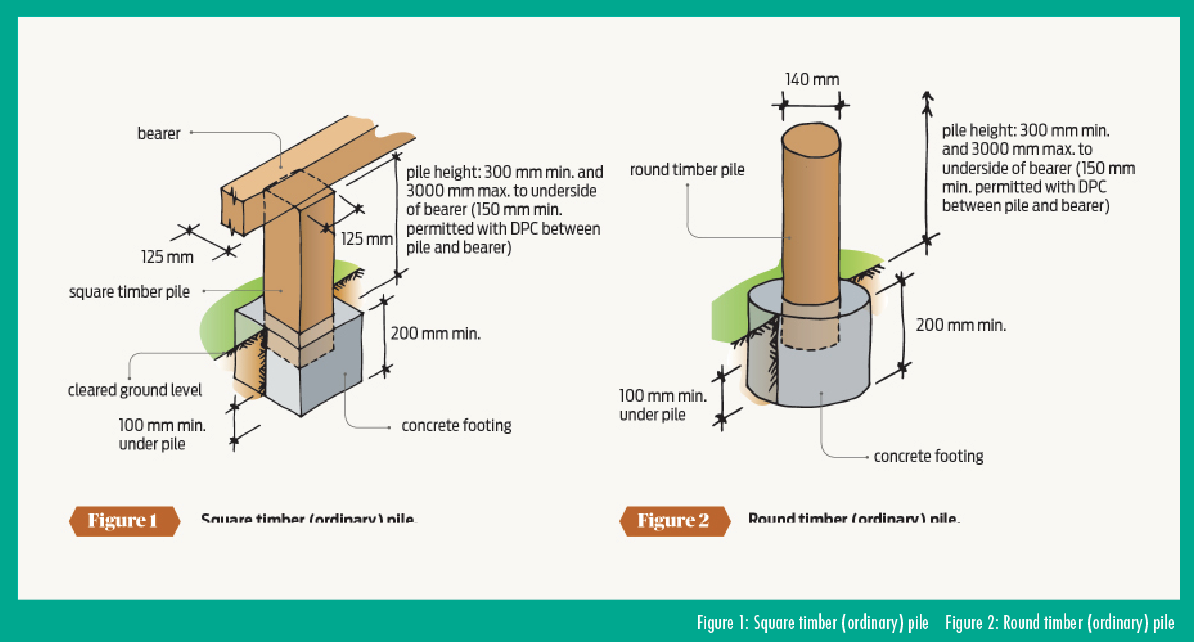
Shows piles supporting bearers and joists for a raised floor.
Timber pile foundation
Reference image
Image / reference: PlaceMakers / Freestanding decks timber pile detail. Treat this as a learning reference and verify the live project against the consented drawings, specification, manufacturer detail, and current NZ requirements.
This PlaceMakers/BRANZ-style pile image is now in the timber pile foundation card because it directly shows timber piles and concrete footings. Use the image to recognise ordinary pile concepts, then verify the project pile type and bracing from NZS 3604/engineer details.
Technical parts to learn
Pile: Learn the term, then confirm exact shape, size, product, laps, clearances, fixings, or tolerances from the project detail.
Bearer: Learn the term, then confirm exact shape, size, product, laps, clearances, fixings, or tolerances from the project detail.
Joist: Learn the term, then confirm exact shape, size, product, laps, clearances, fixings, or tolerances from the project detail.
Bracing: Learn the term, then confirm exact shape, size, product, laps, clearances, fixings, or tolerances from the project detail.
DPC: Learn the term, then confirm exact shape, size, product, laps, clearances, fixings, or tolerances from the project detail.
Subfloor ventilation: Learn the term, then confirm exact shape, size, product, laps, clearances, fixings, or tolerances from the project detail.
Not proven by this image
Pile type and spacing
Embedment/depth
Braced/anchor pile requirements
Timber treatment
Bearer connection
Hidden dimensions, laps, clearances, fixings, cover, tolerances, and product-specific requirements must be checked in the consented drawings, engineer details, manufacturer instructions, and inspection records.
What the CM checks
Check pile layout
Check timber treatment
Check bracing and ventilation
Common defects
Wrong pile location
Missing bracing
Poor ventilation
How to use this image
The photo annotations now describe visible image features only. Replace with the actual consented detail, engineer detail, manufacturer detail, or a marked-up site photo before using on a live project.
Use where the project is within NZS 3604 scope; always confirm against the consented structural drawings and engineer details.
Consented drawings and specifications
The issued consent drawings, stamped specifications, engineering drawings, RFIs, minor variations, and amendments control the specific project.
Insufficient data to verify
Insufficient data to verify — check the consented drawings, project specification, relevant NZ Standard, or council requirement.
Foundations
Reinforced concrete footing
Shows reinforcing steel placement within a concrete footing.
Reinforced concrete footing
Guide sketch
Image / reference: Guide sketch — verify against consented structural drawings. Treat this as a learning reference and verify the live project against the consented drawings, specification, manufacturer detail, and current NZ requirements.
This reinforced footing sketch is used for the reinforced concrete footing card because it shows the footing/reinforcement relationship without importing unrelated site photos. Confirm all steel and concrete details against the structural drawings before work proceeds.
Technical parts to learn
Trench: Learn the term, then confirm exact shape, size, product, laps, clearances, fixings, or tolerances from the project detail.
Bar chairs: Learn the term, then confirm exact shape, size, product, laps, clearances, fixings, or tolerances from the project detail.
Reinforcing: Learn the term, then confirm exact shape, size, product, laps, clearances, fixings, or tolerances from the project detail.
Concrete cover: Learn the term, then confirm exact shape, size, product, laps, clearances, fixings, or tolerances from the project detail.
Starter bars: Learn the term, then confirm exact shape, size, product, laps, clearances, fixings, or tolerances from the project detail.
Inspection point: Learn the term, then confirm exact shape, size, product, laps, clearances, fixings, or tolerances from the project detail.
Not proven by this image
Rebar schedule
Chair/support requirements
Cover
Lap lengths
Engineer/council inspection hold point
Hidden dimensions, laps, clearances, fixings, cover, tolerances, and product-specific requirements must be checked in the consented drawings, engineer details, manufacturer instructions, and inspection records.
What the CM checks
Check bar size/spacing from structural drawings
Check laps/supports
Do not pour before approval
Common defects
Bars missing
No chairs
Wrong starter bar
How to use this image
The photo annotations now describe visible image features only. Replace with the actual consented detail, engineer detail, manufacturer detail, or a marked-up site photo before using on a live project.
This card now uses a direct subfloor framing sketch showing piles, bearer, joists, floor sheet and ventilation space. It avoids using a wall-framing or generic photo for a subfloor topic.
Technical parts to learn
Piles: Learn the term, then confirm exact shape, size, product, laps, clearances, fixings, or tolerances from the project detail.
Bearers: Learn the term, then confirm exact shape, size, product, laps, clearances, fixings, or tolerances from the project detail.
Joists: Learn the term, then confirm exact shape, size, product, laps, clearances, fixings, or tolerances from the project detail.
Blocking: Learn the term, then confirm exact shape, size, product, laps, clearances, fixings, or tolerances from the project detail.
Floor sheets: Learn the term, then confirm exact shape, size, product, laps, clearances, fixings, or tolerances from the project detail.
Bracing: Learn the term, then confirm exact shape, size, product, laps, clearances, fixings, or tolerances from the project detail.
Not proven by this image
Joist/bearer sizes
Spans
Fixings
Subfloor bracing
Ground clearance and ventilation
Hidden dimensions, laps, clearances, fixings, cover, tolerances, and product-specific requirements must be checked in the consented drawings, engineer details, manufacturer instructions, and inspection records.
What the CM checks
Check direction/span from drawings
Check fixings
Check penetrations
Common defects
Bounce/deflection
Wrong spacing
Missing blocking
How to use this image
The photo annotations now describe visible image features only. Replace with the actual consented detail, engineer detail, manufacturer detail, or a marked-up site photo before using on a live project.
This labelled timber wall-framing sketch belongs in the wall framing card because it uses the terms a New Zealand residential construction manager needs on site: top plates, studs, nogs, lintel, bracing sheet area, bottom plate and hold-down zone.
Technical parts to learn
Bottom plate: Learn the term, then confirm exact shape, size, product, laps, clearances, fixings, or tolerances from the project detail.
Stud: Learn the term, then confirm exact shape, size, product, laps, clearances, fixings, or tolerances from the project detail.
Nog: Learn the term, then confirm exact shape, size, product, laps, clearances, fixings, or tolerances from the project detail.
Lintel: Learn the term, then confirm exact shape, size, product, laps, clearances, fixings, or tolerances from the project detail.
Top plate: Learn the term, then confirm exact shape, size, product, laps, clearances, fixings, or tolerances from the project detail.
Hold-down: Learn the term, then confirm exact shape, size, product, laps, clearances, fixings, or tolerances from the project detail.
Not proven by this image
Timber grade/treatment
Nail/bolt fixing pattern
Bracing ratings
Hold-down hardware
Lintel schedule
Hidden dimensions, laps, clearances, fixings, cover, tolerances, and product-specific requirements must be checked in the consented drawings, engineer details, manufacturer instructions, and inspection records.
What the CM checks
Check bracing/lintel schedule
Check plumb/straight
Check service penetrations
Common defects
Missing lintel
Out of plumb
Wrong fixing
How to use this image
The photo annotations now describe visible image features only. Replace with the actual consented detail, engineer detail, manufacturer detail, or a marked-up site photo before using on a live project.
Use where the project is within NZS 3604 scope; always confirm against the consented structural drawings and engineer details.
Consented drawings and specifications
The issued consent drawings, stamped specifications, engineering drawings, RFIs, minor variations, and amendments control the specific project.
Insufficient data to verify
Insufficient data to verify — check the consented drawings, project specification, relevant NZ Standard, or council requirement.
Framing
Bracing wall
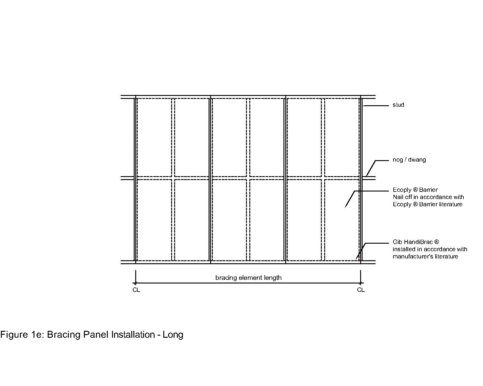
Shows a wall element designed to resist wind/earthquake loads.
Bracing wall
Reference image
Image / reference: CHH Plywood / Ecoply Barrier CAD detail. Treat this as a learning reference and verify the live project against the consented drawings, specification, manufacturer detail, and current NZ requirements.
This Ecoply source detail belongs in the bracing wall card because it shows a bracing panel installation. It is product-specific, so use it as an example only unless Ecoply Barrier is the specified system.
Technical parts to learn
Bracing panel: Learn the term, then confirm exact shape, size, product, laps, clearances, fixings, or tolerances from the project detail.
Hold-down: Learn the term, then confirm exact shape, size, product, laps, clearances, fixings, or tolerances from the project detail.
Sheet fixing: Learn the term, then confirm exact shape, size, product, laps, clearances, fixings, or tolerances from the project detail.
Bottom plate fixing: Learn the term, then confirm exact shape, size, product, laps, clearances, fixings, or tolerances from the project detail.
Load path: Learn the term, then confirm exact shape, size, product, laps, clearances, fixings, or tolerances from the project detail.
Not proven by this image
Project bracing element ID
Specified product
Nail pattern
Hold-downs
Service penetrations through bracing
Hidden dimensions, laps, clearances, fixings, cover, tolerances, and product-specific requirements must be checked in the consented drawings, engineer details, manufacturer instructions, and inspection records.
What the CM checks
Check bracing plan
Check fixing pattern
Protect from service penetrations
Common defects
Wrong sheet/fixings
Hold-down missing
Services cut panel
How to use this image
The photo annotations now describe visible image features only. Replace with the actual consented detail, engineer detail, manufacturer detail, or a marked-up site photo before using on a live project.
Use the exact current installation manual, warranty requirements, BRANZ/Appraisal information where applicable, and product data sheet for the product on site.
Consented drawings and specifications
The issued consent drawings, stamped specifications, engineering drawings, RFIs, minor variations, and amendments control the specific project.
Insufficient data to verify
Insufficient data to verify — check the consented drawings, project specification, relevant NZ Standard, or council requirement.
Roof
Roof trusses
Shows prefabricated roof truss layout and restraint points.
Roof trusses
Guide sketch
Image / reference: Guide sketch — verify against truss supplier documents. Treat this as a learning reference and verify the live project against the consented drawings, specification, manufacturer detail, and current NZ requirements.
This roof truss sketch is placed in the roof trusses card and labels the truss components a beginner needs to recognise. Actual truss positions, bracing and tie-downs are controlled by the truss supplier and consented structural documents.
Technical parts to learn
Truss: Learn the term, then confirm exact shape, size, product, laps, clearances, fixings, or tolerances from the project detail.
Bearing: Learn the term, then confirm exact shape, size, product, laps, clearances, fixings, or tolerances from the project detail.
Webs: Learn the term, then confirm exact shape, size, product, laps, clearances, fixings, or tolerances from the project detail.
Bracing: Learn the term, then confirm exact shape, size, product, laps, clearances, fixings, or tolerances from the project detail.
Tie-down: Learn the term, then confirm exact shape, size, product, laps, clearances, fixings, or tolerances from the project detail.
Purlins: Learn the term, then confirm exact shape, size, product, laps, clearances, fixings, or tolerances from the project detail.
Not proven by this image
Truss ID layout
Temporary/permanent bracing
Fixing/tie-down schedule
Truss modification approval
Supplier install instructions
Hidden dimensions, laps, clearances, fixings, cover, tolerances, and product-specific requirements must be checked in the consented drawings, engineer details, manufacturer instructions, and inspection records.
What the CM checks
Check truss labels
Do not cut trusses
Check bracing/tie-downs
Common defects
Wrong truss location
Cut truss
Missing bracing
How to use this image
The photo annotations now describe visible image features only. Replace with the actual consented detail, engineer detail, manufacturer detail, or a marked-up site photo before using on a live project.
Use where the project is within NZS 3604 scope; always confirm against the consented structural drawings and engineer details.
Consented drawings and specifications
The issued consent drawings, stamped specifications, engineering drawings, RFIs, minor variations, and amendments control the specific project.
Insufficient data to verify
Insufficient data to verify — check the consented drawings, project specification, relevant NZ Standard, or council requirement.
Roof
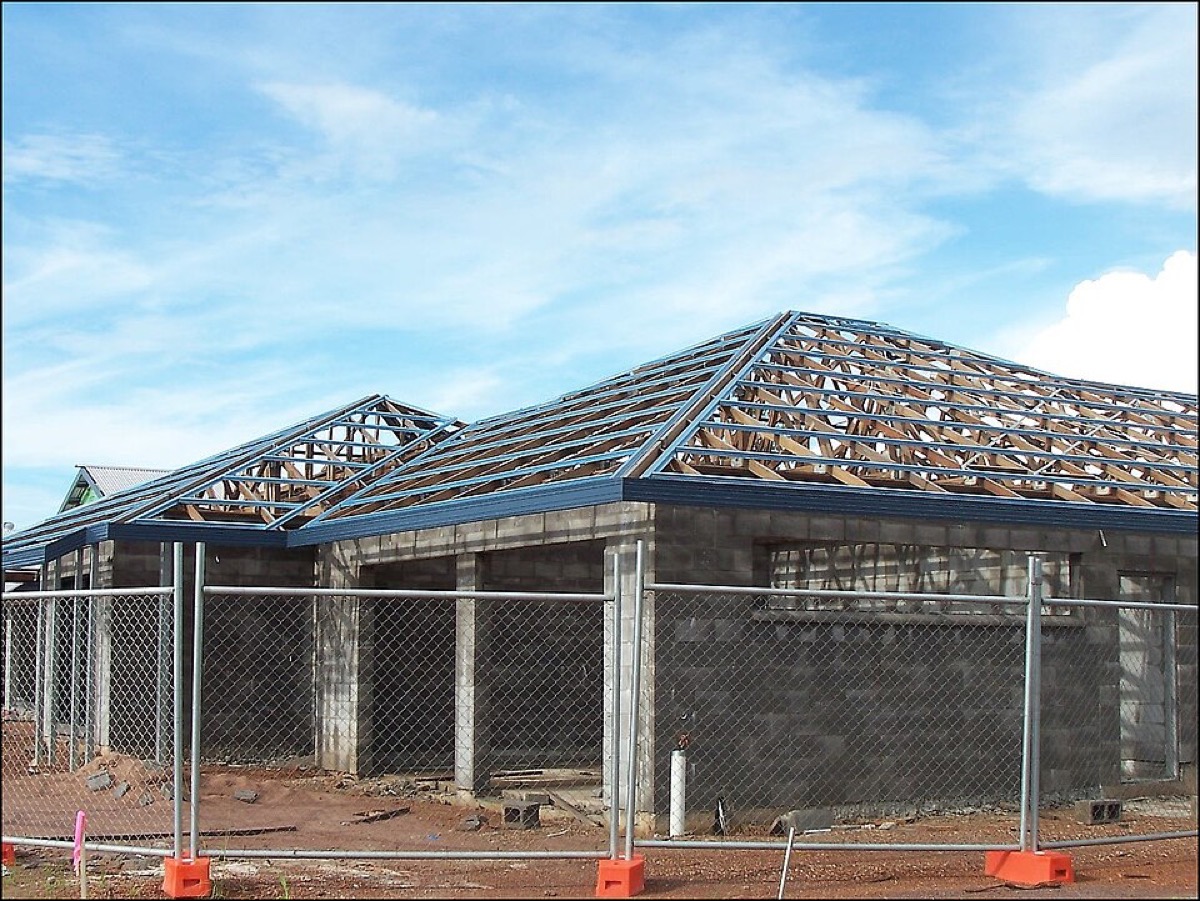
Hip roof
Shows roof planes sloping to eaves on multiple sides.
Hip roof
Reference image
Image / reference: Wikimedia Commons / Domestic roof construction. Treat this as a learning reference and verify the live project against the consented drawings, specification, manufacturer detail, and current NZ requirements.
This image is kept in the hip roof card because it shows a hip roof form and roof support members. It is a visual recognition image; the roof plan and truss layout still control the exact framing.
Technical parts to learn
Hip: Learn the term, then confirm exact shape, size, product, laps, clearances, fixings, or tolerances from the project detail.
Ridge: Learn the term, then confirm exact shape, size, product, laps, clearances, fixings, or tolerances from the project detail.
Valley if present: Learn the term, then confirm exact shape, size, product, laps, clearances, fixings, or tolerances from the project detail.
Eaves: Learn the term, then confirm exact shape, size, product, laps, clearances, fixings, or tolerances from the project detail.
Gutters: Learn the term, then confirm exact shape, size, product, laps, clearances, fixings, or tolerances from the project detail.
Downpipes: Learn the term, then confirm exact shape, size, product, laps, clearances, fixings, or tolerances from the project detail.
Not proven by this image
Hip/valley framing sizes
Tie-downs
Underlay
Flashing laps
Gutter falls
Hidden dimensions, laps, clearances, fixings, cover, tolerances, and product-specific requirements must be checked in the consented drawings, engineer details, manufacturer instructions, and inspection records.
What the CM checks
Check roof drainage
Check flashings
Check safe access
Common defects
Poor valley/hip flashing
Gutter overflow
Roof pitch/product mismatch
How to use this image
The photo annotations now describe visible image features only. Replace with the actual consented detail, engineer detail, manufacturer detail, or a marked-up site photo before using on a live project.
Check stormwater, surface water, drainage paths, and council/engineer stormwater design.
Consented drawings and specifications
The issued consent drawings, stamped specifications, engineering drawings, RFIs, minor variations, and amendments control the specific project.
Insufficient data to verify
Insufficient data to verify — check the consented drawings, project specification, relevant NZ Standard, or council requirement.
Roof
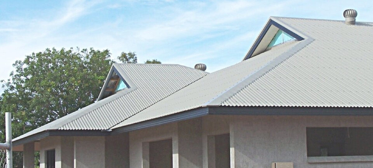
Gable roof
Shows two roof planes meeting at a ridge with gable ends.
Gable roof
Reference image
Image / reference: Wikimedia Commons / Domestic roof construction. Treat this as a learning reference and verify the live project against the consented drawings, specification, manufacturer detail, and current NZ requirements.
This image belongs in the gable roof card because it shows a gabled roof form with metal roof cladding and roof junctions. Use it to identify the shape, then check the roof plan and E2/manufacturer details.
Technical parts to learn
Ridge: Learn the term, then confirm exact shape, size, product, laps, clearances, fixings, or tolerances from the project detail.
Barge: Learn the term, then confirm exact shape, size, product, laps, clearances, fixings, or tolerances from the project detail.
Gable wall: Learn the term, then confirm exact shape, size, product, laps, clearances, fixings, or tolerances from the project detail.
Eaves: Learn the term, then confirm exact shape, size, product, laps, clearances, fixings, or tolerances from the project detail.
Roof underlay: Learn the term, then confirm exact shape, size, product, laps, clearances, fixings, or tolerances from the project detail.
Not proven by this image
Underlay support/laps
Fixing pattern
Ridge/barge/valley details
Ventilation details
Product compatibility
Hidden dimensions, laps, clearances, fixings, cover, tolerances, and product-specific requirements must be checked in the consented drawings, engineer details, manufacturer instructions, and inspection records.
What the CM checks
Check barge/eave details
Check wall/roof junctions
Check tie-downs
Common defects
Barge flashing issue
Gable cladding leak
Poor underlay lap
How to use this image
The photo annotations now describe visible image features only. Replace with the actual consented detail, engineer detail, manufacturer detail, or a marked-up site photo before using on a live project.
The issued consent drawings, stamped specifications, engineering drawings, RFIs, minor variations, and amendments control the specific project.
Insufficient data to verify
Insufficient data to verify — check the consented drawings, project specification, relevant NZ Standard, or council requirement.
Roof
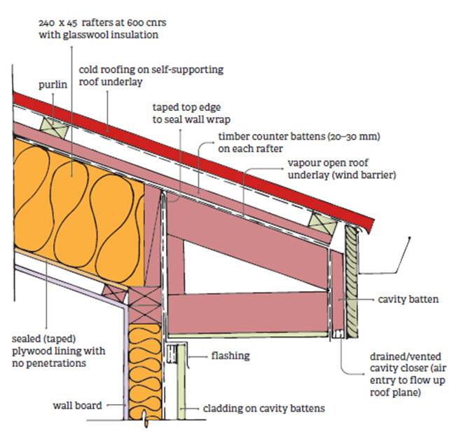
Purlins and battens
Shows roof support members for roofing/cladding products.
Purlins and battens
Reference image
Image / reference: PlaceMakers / BRANZ skillion roof cross-section. Treat this as a learning reference and verify the live project against the consented drawings, specification, manufacturer detail, and current NZ requirements.
This BRANZ/PlaceMakers skillion roof cross-section belongs in the purlins and battens card because it labels purlin/counter-batten/roof-support relationships clearly.
Technical parts to learn
Truss/rafter: Learn the term, then confirm exact shape, size, product, laps, clearances, fixings, or tolerances from the project detail.
Purlin: Learn the term, then confirm exact shape, size, product, laps, clearances, fixings, or tolerances from the project detail.
Batten: Learn the term, then confirm exact shape, size, product, laps, clearances, fixings, or tolerances from the project detail.
Fixing: Learn the term, then confirm exact shape, size, product, laps, clearances, fixings, or tolerances from the project detail.
Roof sheet/tile: Learn the term, then confirm exact shape, size, product, laps, clearances, fixings, or tolerances from the project detail.
Not proven by this image
Exact purlin/batten spacing
Fixing type/length
Roofing product requirements
Ventilation path
Engineer/truss supplier notes
Hidden dimensions, laps, clearances, fixings, cover, tolerances, and product-specific requirements must be checked in the consented drawings, engineer details, manufacturer instructions, and inspection records.
What the CM checks
Check product spacing
Check fixings
Check penetrations
Common defects
Wrong spacing
Poor fixing
Not aligned
How to use this image
The photo annotations now describe visible image features only. Replace with the actual consented detail, engineer detail, manufacturer detail, or a marked-up site photo before using on a live project.
Use the exact current installation manual, warranty requirements, BRANZ/Appraisal information where applicable, and product data sheet for the product on site.
Consented drawings and specifications
The issued consent drawings, stamped specifications, engineering drawings, RFIs, minor variations, and amendments control the specific project.
Insufficient data to verify
Insufficient data to verify — check the consented drawings, project specification, relevant NZ Standard, or council requirement.
Envelope
Roof underlay
Shows roof underlay beneath roof cladding.
Roof underlay
Reference image
Image / reference: PlaceMakers / BRANZ skillion roof cross-section. Treat this as a learning reference and verify the live project against the consented drawings, specification, manufacturer detail, and current NZ requirements.
This BRANZ/PlaceMakers detail belongs in the roof underlay card because it labels roof underlay and shows how it sits in a roof build-up. It is not a universal roof detail.
Technical parts to learn
Underlay: Learn the term, then confirm exact shape, size, product, laps, clearances, fixings, or tolerances from the project detail.
Laps: Learn the term, then confirm exact shape, size, product, laps, clearances, fixings, or tolerances from the project detail.
Support: Learn the term, then confirm exact shape, size, product, laps, clearances, fixings, or tolerances from the project detail.
Penetrations: Learn the term, then confirm exact shape, size, product, laps, clearances, fixings, or tolerances from the project detail.
Gutter edge: Learn the term, then confirm exact shape, size, product, laps, clearances, fixings, or tolerances from the project detail.
Not proven by this image
Underlay product
Lap direction
Support/sag
Penetration sealing
Eaves/gutter edge treatment
Hidden dimensions, laps, clearances, fixings, cover, tolerances, and product-specific requirements must be checked in the consented drawings, engineer details, manufacturer instructions, and inspection records.
What the CM checks
Check lap direction
Repair tears
Protect before roofing
Common defects
Torn underlay
Reverse lap
Water trapped
How to use this image
The photo annotations now describe visible image features only. Replace with the actual consented detail, engineer detail, manufacturer detail, or a marked-up site photo before using on a live project.
Use the exact current installation manual, warranty requirements, BRANZ/Appraisal information where applicable, and product data sheet for the product on site.
Consented drawings and specifications
The issued consent drawings, stamped specifications, engineering drawings, RFIs, minor variations, and amendments control the specific project.
Insufficient data to verify
Insufficient data to verify — check the consented drawings, project specification, relevant NZ Standard, or council requirement.
Envelope
Wall underlay
Shows flexible or rigid wall underlay behind cladding.
Wall underlay
Reference image
Image / reference: CHH Plywood / Ecoply Barrier wall opening detail. Treat this as a learning reference and verify the live project against the consented drawings, specification, manufacturer detail, and current NZ requirements.
This Ecoply wall-opening detail belongs in the wall underlay card because it shows a wall barrier/opening system rather than a random house-wrap photo. It is product-specific and must match the specified wall underlay or rigid air barrier.
Technical parts to learn
Frame: Learn the term, then confirm exact shape, size, product, laps, clearances, fixings, or tolerances from the project detail.
Underlay: Learn the term, then confirm exact shape, size, product, laps, clearances, fixings, or tolerances from the project detail.
Tapes: Learn the term, then confirm exact shape, size, product, laps, clearances, fixings, or tolerances from the project detail.
Penetrations: Learn the term, then confirm exact shape, size, product, laps, clearances, fixings, or tolerances from the project detail.
Window opening: Learn the term, then confirm exact shape, size, product, laps, clearances, fixings, or tolerances from the project detail.
Not proven by this image
Specified underlay/barrier
Tape compatibility
Opening treatment
Exposure limits
Inspection evidence before cladding
Hidden dimensions, laps, clearances, fixings, cover, tolerances, and product-specific requirements must be checked in the consented drawings, engineer details, manufacturer instructions, and inspection records.
What the CM checks
Check laps/tapes
Repair holes
Check exposure limits
Common defects
Tears
Poor taping
Penetrations unsealed
How to use this image
The photo annotations now describe visible image features only. Replace with the actual consented detail, engineer detail, manufacturer detail, or a marked-up site photo before using on a live project.
Use the exact current installation manual, warranty requirements, BRANZ/Appraisal information where applicable, and product data sheet for the product on site.
Consented drawings and specifications
The issued consent drawings, stamped specifications, engineering drawings, RFIs, minor variations, and amendments control the specific project.
Insufficient data to verify
Insufficient data to verify — check the consented drawings, project specification, relevant NZ Standard, or council requirement.
Envelope
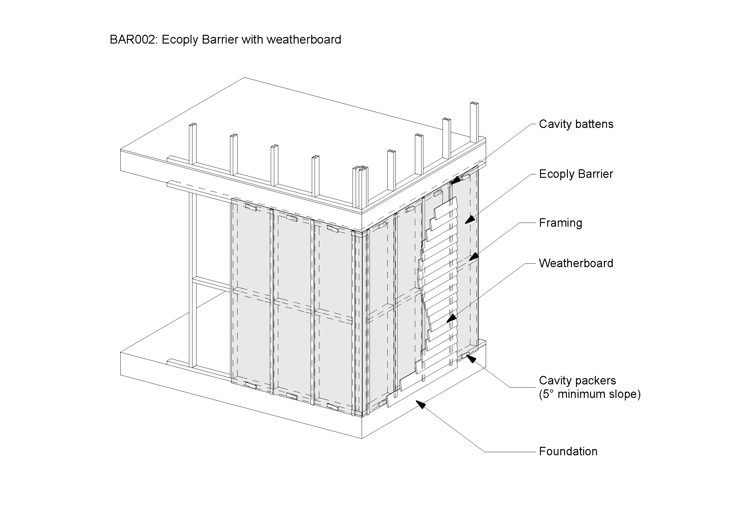
Drained cavity
Shows cavity battens and drainage/ventilation path behind cladding.
Drained cavity
Reference image
Image / reference: CHH Plywood / Ecoply Barrier with weatherboard detail. Treat this as a learning reference and verify the live project against the consented drawings, specification, manufacturer detail, and current NZ requirements.
This Ecoply weatherboard-system detail belongs in the drained cavity card because it shows the relationship between cladding, cavity battens and the wall barrier. Use the project cladding manufacturer's cavity detail for the actual build.
Technical parts to learn
Underlay: Learn the term, then confirm exact shape, size, product, laps, clearances, fixings, or tolerances from the project detail.
Cavity batten: Learn the term, then confirm exact shape, size, product, laps, clearances, fixings, or tolerances from the project detail.
Cavity closer: Learn the term, then confirm exact shape, size, product, laps, clearances, fixings, or tolerances from the project detail.
Cladding: Learn the term, then confirm exact shape, size, product, laps, clearances, fixings, or tolerances from the project detail.
Drainage path: Learn the term, then confirm exact shape, size, product, laps, clearances, fixings, or tolerances from the project detail.
Not proven by this image
Cavity batten material/thickness
Cavity closer
Drainage/ventilation path
Base drainage opening
Product-specific fixings
Hidden dimensions, laps, clearances, fixings, cover, tolerances, and product-specific requirements must be checked in the consented drawings, engineer details, manufacturer instructions, and inspection records.
What the CM checks
Check base drainage
Check around openings
Photograph before cladding
Common defects
Blocked cavity
Missing batten
Wrong closer
How to use this image
The photo annotations now describe visible image features only. Replace with the actual consented detail, engineer detail, manufacturer detail, or a marked-up site photo before using on a live project.
Use the exact current installation manual, warranty requirements, BRANZ/Appraisal information where applicable, and product data sheet for the product on site.
Consented drawings and specifications
The issued consent drawings, stamped specifications, engineering drawings, RFIs, minor variations, and amendments control the specific project.
Insufficient data to verify
Insufficient data to verify — check the consented drawings, project specification, relevant NZ Standard, or council requirement.
Envelope
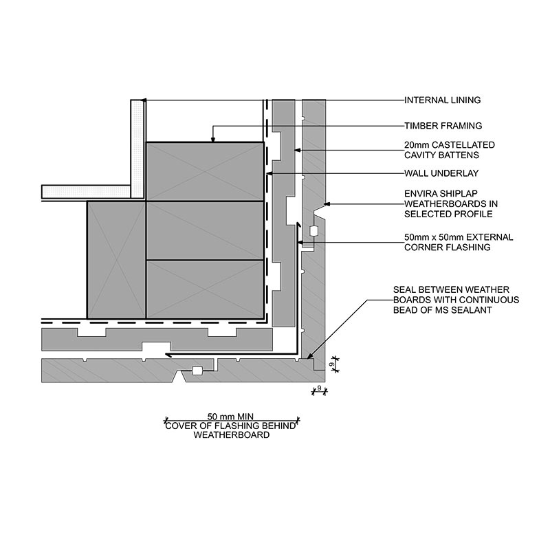
Weatherboard cladding
Shows weatherboard laps, fixings, corners, and clearances.
Weatherboard cladding
Reference image
Image / reference: CHH Plywood / Ecoply Barrier with weatherboard detail. Treat this as a learning reference and verify the live project against the consented drawings, specification, manufacturer detail, and current NZ requirements.
This weatherboard-system detail is placed in the weatherboard cladding card because it directly shows weatherboard cladding and cavity build-up. Confirm the actual weatherboard profile, laps, fixings and clearances from the specified product details.
Technical parts to learn
Weatherboard: Learn the term, then confirm exact shape, size, product, laps, clearances, fixings, or tolerances from the project detail.
Lap: Learn the term, then confirm exact shape, size, product, laps, clearances, fixings, or tolerances from the project detail.
Fixing: Learn the term, then confirm exact shape, size, product, laps, clearances, fixings, or tolerances from the project detail.
Cavity: Learn the term, then confirm exact shape, size, product, laps, clearances, fixings, or tolerances from the project detail.
Scriber/corner: Learn the term, then confirm exact shape, size, product, laps, clearances, fixings, or tolerances from the project detail.
Base clearance: Learn the term, then confirm exact shape, size, product, laps, clearances, fixings, or tolerances from the project detail.
Not proven by this image
Weatherboard profile
Lap
Fixing line
Cut-end sealing
Ground/deck clearances
Hidden dimensions, laps, clearances, fixings, cover, tolerances, and product-specific requirements must be checked in the consented drawings, engineer details, manufacturer instructions, and inspection records.
What the CM checks
Check laps/fixings
Check cut-end sealing
Check clearances
Common defects
Low clearance
Poor joints
Unsealed cuts
How to use this image
The photo annotations now describe visible image features only. Replace with the actual consented detail, engineer detail, manufacturer detail, or a marked-up site photo before using on a live project.
Use the exact current installation manual, warranty requirements, BRANZ/Appraisal information where applicable, and product data sheet for the product on site.
Consented drawings and specifications
The issued consent drawings, stamped specifications, engineering drawings, RFIs, minor variations, and amendments control the specific project.
Insufficient data to verify
Insufficient data to verify — check the consented drawings, project specification, relevant NZ Standard, or council requirement.
Envelope
Brick veneer
Shows brick veneer cavity, ties, flashing, and weepholes.
Brick veneer
Reference image
Image / reference: Niagara Envira CAD / Masonry veneer below detail. Treat this as a learning reference and verify the live project against the consented drawings, specification, manufacturer detail, and current NZ requirements.
This Niagara masonry veneer below detail belongs in the brick veneer card because it shows the relationship between brick veneer and the cladding/wall system. It is a product detail example, not a complete masonry veneer standard.
Technical parts to learn
Brick veneer: Learn the term, then confirm exact shape, size, product, laps, clearances, fixings, or tolerances from the project detail.
Cavity: Learn the term, then confirm exact shape, size, product, laps, clearances, fixings, or tolerances from the project detail.
Wall ties: Learn the term, then confirm exact shape, size, product, laps, clearances, fixings, or tolerances from the project detail.
Weepholes: Learn the term, then confirm exact shape, size, product, laps, clearances, fixings, or tolerances from the project detail.
Flashing: Learn the term, then confirm exact shape, size, product, laps, clearances, fixings, or tolerances from the project detail.
Frame: Learn the term, then confirm exact shape, size, product, laps, clearances, fixings, or tolerances from the project detail.
Not proven by this image
Wall ties
Cavity width/cleanliness
Weepholes
Shelf/base flashing
Mortar bridging
Hidden dimensions, laps, clearances, fixings, cover, tolerances, and product-specific requirements must be checked in the consented drawings, engineer details, manufacturer instructions, and inspection records.
What the CM checks
Check cavity clean
Check ties
Check weep holes/flashings
Common defects
Mortar bridging
Missing ties
Blocked weepholes
How to use this image
The photo annotations now describe visible image features only. Replace with the actual consented detail, engineer detail, manufacturer detail, or a marked-up site photo before using on a live project.
The issued consent drawings, stamped specifications, engineering drawings, RFIs, minor variations, and amendments control the specific project.
Insufficient data to verify
Insufficient data to verify — check the consented drawings, project specification, relevant NZ Standard, or council requirement.
Envelope
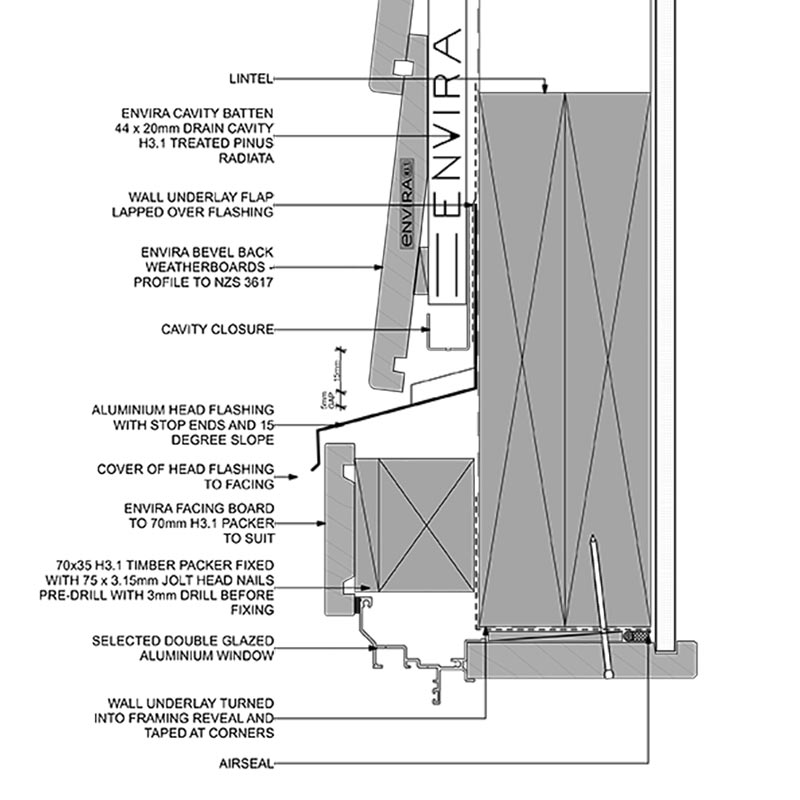
Window head flashing
Shows flashing above exterior joinery.
Window head flashing
Reference image
Image / reference: Niagara Envira CAD / Window head detail. Treat this as a learning reference and verify the live project against the consented drawings, specification, manufacturer detail, and current NZ requirements.
This Niagara window head detail is now placed in the window head flashing card. The image itself labels the head/joinery/cladding relationship, so the card no longer points to an unrelated window photo.
Technical parts to learn
Cladding: Learn the term, then confirm exact shape, size, product, laps, clearances, fixings, or tolerances from the project detail.
Head flashing: Learn the term, then confirm exact shape, size, product, laps, clearances, fixings, or tolerances from the project detail.
End dam: Learn the term, then confirm exact shape, size, product, laps, clearances, fixings, or tolerances from the project detail.
Cavity: Learn the term, then confirm exact shape, size, product, laps, clearances, fixings, or tolerances from the project detail.
Window frame: Learn the term, then confirm exact shape, size, product, laps, clearances, fixings, or tolerances from the project detail.
Air seal: Learn the term, then confirm exact shape, size, product, laps, clearances, fixings, or tolerances from the project detail.
Not proven by this image
Specified joinery system
Head flashing size/slope
End dams
Lap sequence
Cavity drainage path
Hidden dimensions, laps, clearances, fixings, cover, tolerances, and product-specific requirements must be checked in the consented drawings, engineer details, manufacturer instructions, and inspection records.
What the CM checks
Check lap sequence
Check length/end dams from detail
Photograph before cladding
Common defects
Flashing too short
Reverse lap
No drainage path
How to use this image
The photo annotations now describe visible image features only. Replace with the actual consented detail, engineer detail, manufacturer detail, or a marked-up site photo before using on a live project.
Use the exact current installation manual, warranty requirements, BRANZ/Appraisal information where applicable, and product data sheet for the product on site.
Consented drawings and specifications
The issued consent drawings, stamped specifications, engineering drawings, RFIs, minor variations, and amendments control the specific project.
Insufficient data to verify
Insufficient data to verify — check the consented drawings, project specification, relevant NZ Standard, or council requirement.
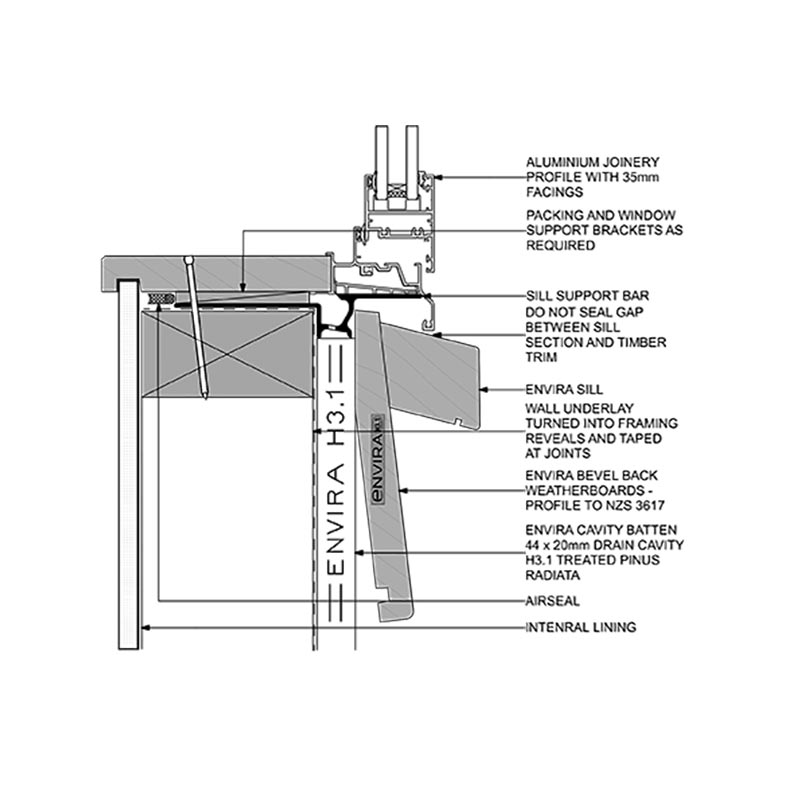
Envelope
Window sill flashing
Shows sill support and water path below joinery.
Window sill flashing
Reference image
Image / reference: Niagara Envira CAD / Window sill support bar detail. Treat this as a learning reference and verify the live project against the consented drawings, specification, manufacturer detail, and current NZ requirements.
This Niagara window sill support-bar detail is now placed in the window sill flashing card. Use it to learn sill support and drainage relationships, then verify the exact joinery/cladding detail for the project.
Technical parts to learn
Sill tray/flashing: Learn the term, then confirm exact shape, size, product, laps, clearances, fixings, or tolerances from the project detail.
Packers: Learn the term, then confirm exact shape, size, product, laps, clearances, fixings, or tolerances from the project detail.
Support: Learn the term, then confirm exact shape, size, product, laps, clearances, fixings, or tolerances from the project detail.
Cavity: Learn the term, then confirm exact shape, size, product, laps, clearances, fixings, or tolerances from the project detail.
Cladding: Learn the term, then confirm exact shape, size, product, laps, clearances, fixings, or tolerances from the project detail.
Drainage path: Learn the term, then confirm exact shape, size, product, laps, clearances, fixings, or tolerances from the project detail.
Not proven by this image
Sill tray/support type
Packers
Air seal
Drainage gap
Product-specific sill detail
Hidden dimensions, laps, clearances, fixings, cover, tolerances, and product-specific requirements must be checked in the consented drawings, engineer details, manufacturer instructions, and inspection records.
What the CM checks
Check support and packers
Check sill tape/tray
Check no blockage
Common defects
Unsupported sill
Tape failure
Blocked drainage
How to use this image
The photo annotations now describe visible image features only. Replace with the actual consented detail, engineer detail, manufacturer detail, or a marked-up site photo before using on a live project.
Use the exact current installation manual, warranty requirements, BRANZ/Appraisal information where applicable, and product data sheet for the product on site.
Consented drawings and specifications
The issued consent drawings, stamped specifications, engineering drawings, RFIs, minor variations, and amendments control the specific project.
Insufficient data to verify
Insufficient data to verify — check the consented drawings, project specification, relevant NZ Standard, or council requirement.
Envelope
External corner detail
Shows how cladding and cavity continue around an outside corner.
External corner detail
Reference image
Image / reference: Niagara Envira CAD / External corner lapped detail. Treat this as a learning reference and verify the live project against the consented drawings, specification, manufacturer detail, and current NZ requirements.
This Niagara external corner detail belongs in the external corner card because it directly shows an external cladding corner. Use the specified cladding system's corner detail for the actual project.
Technical parts to learn
Corner trim: Learn the term, then confirm exact shape, size, product, laps, clearances, fixings, or tolerances from the project detail.
Cavity battens: Learn the term, then confirm exact shape, size, product, laps, clearances, fixings, or tolerances from the project detail.
Underlay: Learn the term, then confirm exact shape, size, product, laps, clearances, fixings, or tolerances from the project detail.
Cladding ends: Learn the term, then confirm exact shape, size, product, laps, clearances, fixings, or tolerances from the project detail.
Fixings: Learn the term, then confirm exact shape, size, product, laps, clearances, fixings, or tolerances from the project detail.
Not proven by this image
Corner trim/scriber type
Cavity continuity
Cut-end coating
Fixings
Sealant/back-flashing requirements
Hidden dimensions, laps, clearances, fixings, cover, tolerances, and product-specific requirements must be checked in the consented drawings, engineer details, manufacturer instructions, and inspection records.
What the CM checks
Check cavity continuity
Check cut-end coating
Check trim/joint detail
Common defects
Gaps
Unsealed ends
Blocked cavity
How to use this image
The photo annotations now describe visible image features only. Replace with the actual consented detail, engineer detail, manufacturer detail, or a marked-up site photo before using on a live project.
Use the exact current installation manual, warranty requirements, BRANZ/Appraisal information where applicable, and product data sheet for the product on site.
Consented drawings and specifications
The issued consent drawings, stamped specifications, engineering drawings, RFIs, minor variations, and amendments control the specific project.
Insufficient data to verify
Insufficient data to verify — check the consented drawings, project specification, relevant NZ Standard, or council requirement.
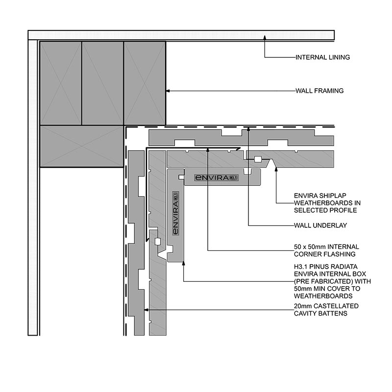
Envelope
Internal corner detail
Shows cladding/wall junction at inside corners.
Internal corner detail
Reference image
Image / reference: Niagara Envira CAD / Internal corner boxed detail. Treat this as a learning reference and verify the live project against the consented drawings, specification, manufacturer detail, and current NZ requirements.
This Niagara internal corner detail belongs in the internal corner card because it directly shows an internal cladding corner. It is product-specific and must be replaced by the specified system if different.
Technical parts to learn
Back flashing: Learn the term, then confirm exact shape, size, product, laps, clearances, fixings, or tolerances from the project detail.
Cladding edges: Learn the term, then confirm exact shape, size, product, laps, clearances, fixings, or tolerances from the project detail.
Cavity: Learn the term, then confirm exact shape, size, product, laps, clearances, fixings, or tolerances from the project detail.
Sealant if specified: Learn the term, then confirm exact shape, size, product, laps, clearances, fixings, or tolerances from the project detail.
Drainage path: Learn the term, then confirm exact shape, size, product, laps, clearances, fixings, or tolerances from the project detail.
Not proven by this image
Back flashing
Cavity drainage route
Cladding edge treatment
Sealant/system detail
Clean junction before close-up
Hidden dimensions, laps, clearances, fixings, cover, tolerances, and product-specific requirements must be checked in the consented drawings, engineer details, manufacturer instructions, and inspection records.
What the CM checks
Check water path
Check flashings before cladding
Check clean junction
Common defects
Water trap
Missing back flashing
Sealant-only detail
How to use this image
The photo annotations now describe visible image features only. Replace with the actual consented detail, engineer detail, manufacturer detail, or a marked-up site photo before using on a live project.
Use the exact current installation manual, warranty requirements, BRANZ/Appraisal information where applicable, and product data sheet for the product on site.
Consented drawings and specifications
The issued consent drawings, stamped specifications, engineering drawings, RFIs, minor variations, and amendments control the specific project.
Insufficient data to verify
Insufficient data to verify — check the consented drawings, project specification, relevant NZ Standard, or council requirement.
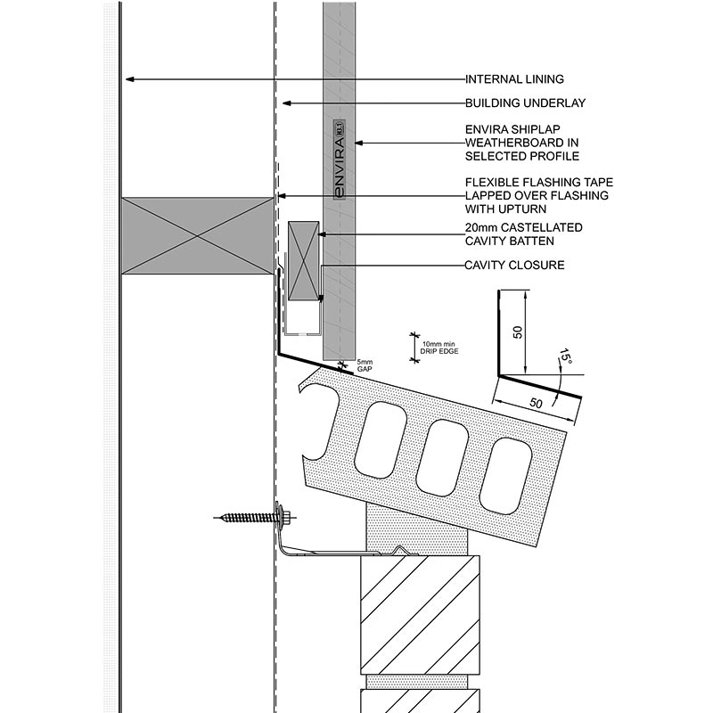
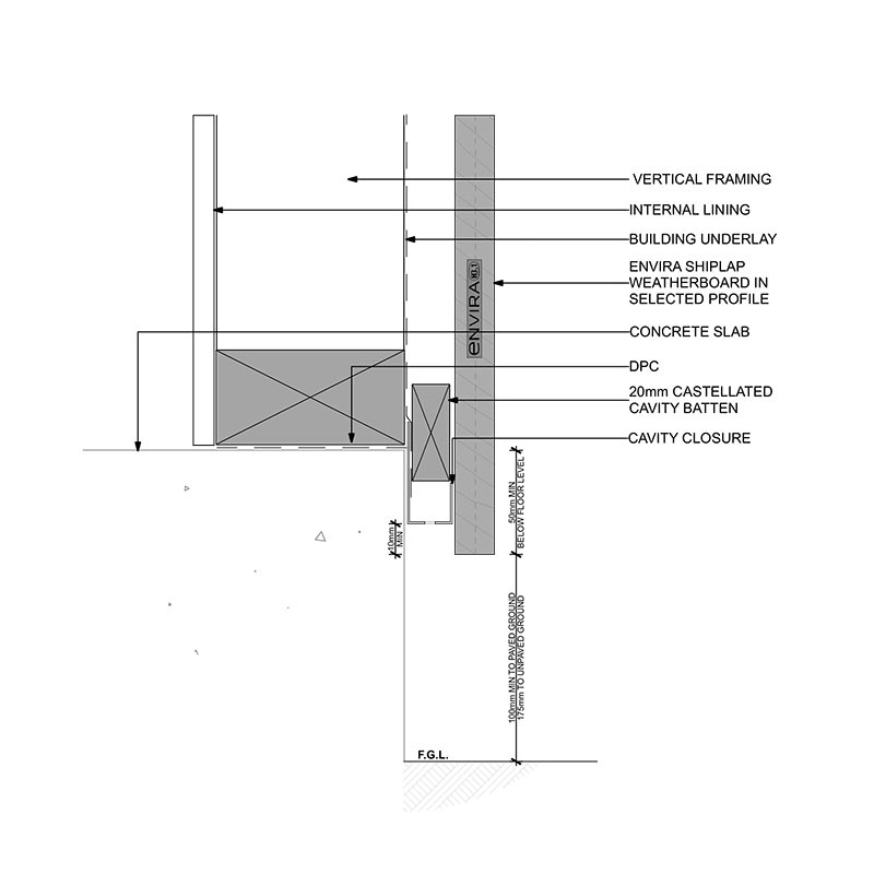
Envelope
Cladding base detail
Shows the bottom of cladding, cavity closer, and clearance to ground/deck.
Cladding base detail
Reference image
Image / reference: Niagara Envira CAD / Foundation concrete detail. Treat this as a learning reference and verify the live project against the consented drawings, specification, manufacturer detail, and current NZ requirements.
This Niagara foundation concrete detail belongs in the cladding base card because it shows the wall/cladding/foundation base relationship. Confirm actual cladding clearances and cavity closure from E2 details and the product manual.
Technical parts to learn
Cladding: Learn the term, then confirm exact shape, size, product, laps, clearances, fixings, or tolerances from the project detail.
Cavity closer: Learn the term, then confirm exact shape, size, product, laps, clearances, fixings, or tolerances from the project detail.
Base flashing: Learn the term, then confirm exact shape, size, product, laps, clearances, fixings, or tolerances from the project detail.
Ground/deck level: Learn the term, then confirm exact shape, size, product, laps, clearances, fixings, or tolerances from the project detail.
Drainage gap: Learn the term, then confirm exact shape, size, product, laps, clearances, fixings, or tolerances from the project detail.
Not proven by this image
Finished ground level
Cavity closer
Base flashing
Drainage openings
B2 durability/product requirements
Hidden dimensions, laps, clearances, fixings, cover, tolerances, and product-specific requirements must be checked in the consented drawings, engineer details, manufacturer instructions, and inspection records.
What the CM checks
Check finished ground levels
Check cavity outlet
Do not bury base detail
Common defects
Clearance too low
Blocked cavity
Landscaping against wall
How to use this image
The photo annotations now describe visible image features only. Replace with the actual consented detail, engineer detail, manufacturer detail, or a marked-up site photo before using on a live project.
This card now uses a roof-water sketch instead of relying on a cropped generic photo. It shows the gutter, outlet, downpipe and stormwater connection in the right card.
Technical parts to learn
Roof: Learn the term, then confirm exact shape, size, product, laps, clearances, fixings, or tolerances from the project detail.
Gutter: Learn the term, then confirm exact shape, size, product, laps, clearances, fixings, or tolerances from the project detail.
Outlet: Learn the term, then confirm exact shape, size, product, laps, clearances, fixings, or tolerances from the project detail.
Downpipe: Learn the term, then confirm exact shape, size, product, laps, clearances, fixings, or tolerances from the project detail.
Stormwater drain: Learn the term, then confirm exact shape, size, product, laps, clearances, fixings, or tolerances from the project detail.
Overflow path: Learn the term, then confirm exact shape, size, product, laps, clearances, fixings, or tolerances from the project detail.
Not proven by this image
Gutter fall
Overflow provision
Downpipe size
Stormwater connection
Bracket spacing
Hidden dimensions, laps, clearances, fixings, cover, tolerances, and product-specific requirements must be checked in the consented drawings, engineer details, manufacturer instructions, and inspection records.
What the CM checks
Check falls and outlets
Check connection
Check overflow risk
Common defects
Ponding gutter
Wrong discharge
Blocked outlet
How to use this image
The photo annotations now describe visible image features only. Replace with the actual consented detail, engineer detail, manufacturer detail, or a marked-up site photo before using on a live project.
Check stormwater, surface water, drainage paths, and council/engineer stormwater design.
Manufacturer specification
Use the exact current installation manual, warranty requirements, BRANZ/Appraisal information where applicable, and product data sheet for the product on site.
Consented drawings and specifications
The issued consent drawings, stamped specifications, engineering drawings, RFIs, minor variations, and amendments control the specific project.
Insufficient data to verify
Insufficient data to verify — check the consented drawings, project specification, relevant NZ Standard, or council requirement.
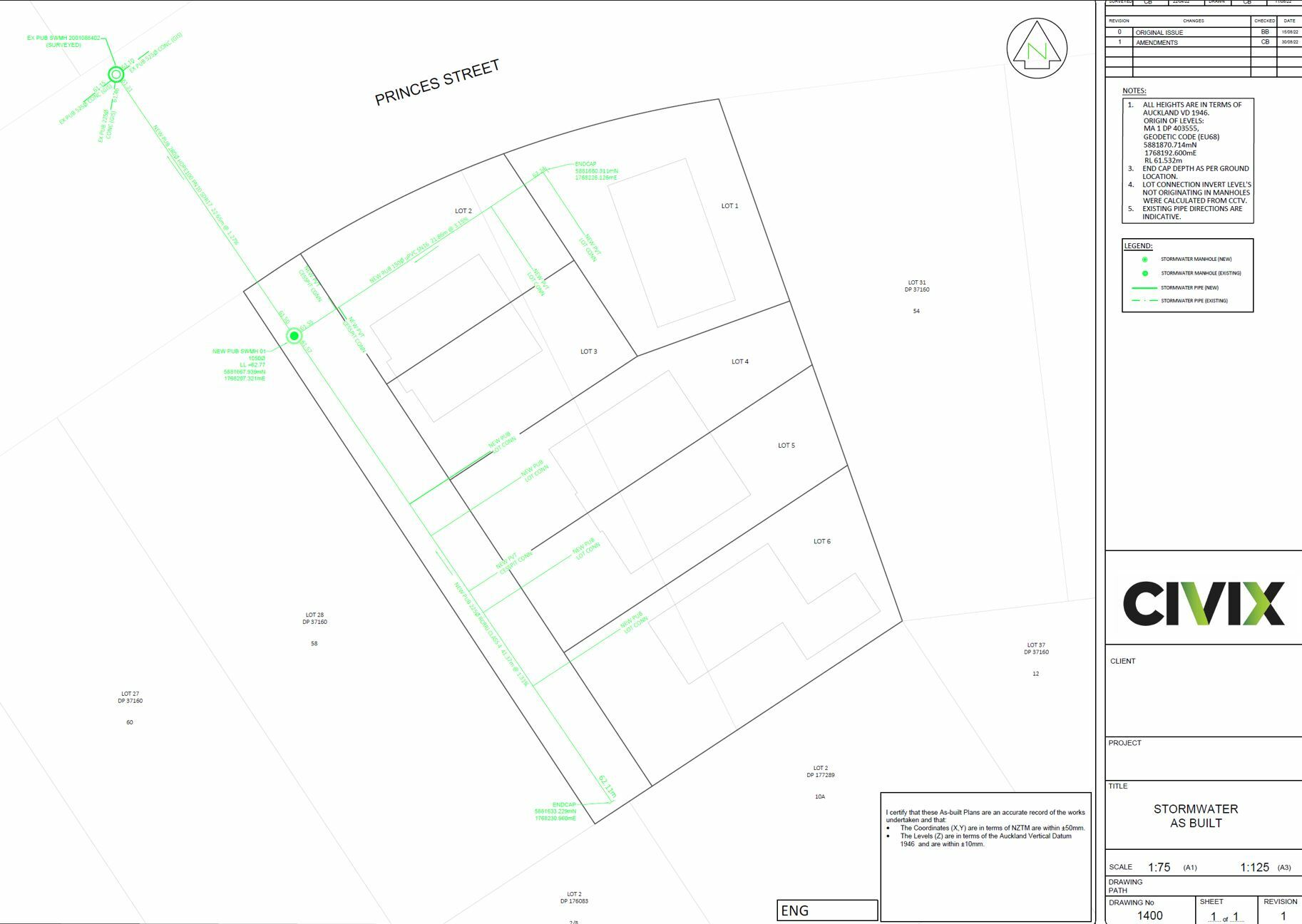
Drainage
Drainage layout
Shows wastewater and stormwater pipe routes, access points, and connections.
Drainage layout
Reference image
Image / reference: Civix / As-built survey example. Treat this as a learning reference and verify the live project against the consented drawings, specification, manufacturer detail, and current NZ requirements.
This Civix as-built drawing example belongs in the drainage layout card because it shows plan-based drainage routes, manholes and connection information. Use it to learn what a drainage/as-built drawing looks like.
Technical parts to learn
Pipe run: Learn the term, then confirm exact shape, size, product, laps, clearances, fixings, or tolerances from the project detail.
Falls: Learn the term, then confirm exact shape, size, product, laps, clearances, fixings, or tolerances from the project detail.
Inspection opening: Learn the term, then confirm exact shape, size, product, laps, clearances, fixings, or tolerances from the project detail.
Gully: Learn the term, then confirm exact shape, size, product, laps, clearances, fixings, or tolerances from the project detail.
Manhole: Learn the term, then confirm exact shape, size, product, laps, clearances, fixings, or tolerances from the project detail.
Connection: Learn the term, then confirm exact shape, size, product, laps, clearances, fixings, or tolerances from the project detail.
Not proven by this image
Project pipe routes
Pipe falls/invert levels
Inspection openings
Council connection points
As-built survey certification
Hidden dimensions, laps, clearances, fixings, cover, tolerances, and product-specific requirements must be checked in the consented drawings, engineer details, manufacturer instructions, and inspection records.
What the CM checks
Check route before trenching
Check inspection/openings
Record as-builts
Common defects
Wrong fall
Buried access
Service clash
How to use this image
The photo annotations now describe visible image features only. Replace with the actual consented detail, engineer detail, manufacturer detail, or a marked-up site photo before using on a live project.
Auckland Council explains local building consent processes, CCC, related certificates, producer statements, LBP notification, and whether resource consent may also be needed.
Consented drawings and specifications
The issued consent drawings, stamped specifications, engineering drawings, RFIs, minor variations, and amendments control the specific project.
Insufficient data to verify
Insufficient data to verify — check the consented drawings, project specification, relevant NZ Standard, or council requirement.
Services
Services trench
Shows underground trench route for water, power, gas, data, or drainage services.
This council underground-services diagram belongs in the services trench card because it shows how water, wastewater, stormwater, gas, cable and telecom services can sit below roads/berms. Actual trench depths and separations must come from service owners and project requirements.
Technical parts to learn
Trench: Learn the term, then confirm exact shape, size, product, laps, clearances, fixings, or tolerances from the project detail.
Bedding: Learn the term, then confirm exact shape, size, product, laps, clearances, fixings, or tolerances from the project detail.
Service pipe/duct: Learn the term, then confirm exact shape, size, product, laps, clearances, fixings, or tolerances from the project detail.
Warning tape: Learn the term, then confirm exact shape, size, product, laps, clearances, fixings, or tolerances from the project detail.
Backfill: Learn the term, then confirm exact shape, size, product, laps, clearances, fixings, or tolerances from the project detail.
Surface: Learn the term, then confirm exact shape, size, product, laps, clearances, fixings, or tolerances from the project detail.
Not proven by this image
BeforeUdig/service locates
Service depth/cover
Separation distances
Bedding/backfill
Warning tape and reinstatement
Hidden dimensions, laps, clearances, fixings, cover, tolerances, and product-specific requirements must be checked in the consented drawings, engineer details, manufacturer instructions, and inspection records.
What the CM checks
Locate existing services
Check separation/protection
Photograph before backfill
Common defects
Service strike
Wrong cover
No warning tape
How to use this image
The photo annotations now describe visible image features only. Replace with the actual consented detail, engineer detail, manufacturer detail, or a marked-up site photo before using on a live project.
Use for excavation risk management, trenching, collapse, services, access, exclusion, and emergency planning.
Consented drawings and specifications
The issued consent drawings, stamped specifications, engineering drawings, RFIs, minor variations, and amendments control the specific project.
Consented drawings and specifications
The issued consent drawings, stamped specifications, engineering drawings, RFIs, minor variations, and amendments control the specific project.
Insufficient data to verify
Insufficient data to verify — check the consented drawings, project specification, relevant NZ Standard, or council requirement.
Interior
Bathroom waterproofing
Shows wet-area membrane, corners, wastes, and wall/floor junctions.
Bathroom waterproofing
Reference image
Image / reference: Wellington Tilers / E3-AS1 waterproofing overview. Treat this as a learning reference and verify the live project against the consented drawings, specification, manufacturer detail, and current NZ requirements.
This waterproofing zones image belongs in the bathroom waterproofing card because it shows the wet-area membrane concept in the correct bathroom context. Verify all heights, substrate, membrane system and PS3 requirements from E3/AS1, the Code of Practice, product literature and consented drawings.
Technical parts to learn
Substrate: Learn the term, then confirm exact shape, size, product, laps, clearances, fixings, or tolerances from the project detail.
Primer: Learn the term, then confirm exact shape, size, product, laps, clearances, fixings, or tolerances from the project detail.
Bond breaker: Learn the term, then confirm exact shape, size, product, laps, clearances, fixings, or tolerances from the project detail.
Membrane: Learn the term, then confirm exact shape, size, product, laps, clearances, fixings, or tolerances from the project detail.
Waste flange: Learn the term, then confirm exact shape, size, product, laps, clearances, fixings, or tolerances from the project detail.
Tile system: Learn the term, then confirm exact shape, size, product, laps, clearances, fixings, or tolerances from the project detail.
Not proven by this image
Specified membrane system
Substrate
Bond breakers/tapes
Dry film thickness
Flood test/declaration
Hidden dimensions, laps, clearances, fixings, cover, tolerances, and product-specific requirements must be checked in the consented drawings, engineer details, manufacturer instructions, and inspection records.
What the CM checks
Check substrate dry/clean
Check membrane before tiling
Collect declaration
Common defects
Pinholes
No bond breaker
Tiling too early
How to use this image
The photo annotations now describe visible image features only. Replace with the actual consented detail, engineer detail, manufacturer detail, or a marked-up site photo before using on a live project.
Check wet-area surfaces, ventilation, waterproofing details, and manufacturer systems against consented documents.
Manufacturer specification
Use the exact current installation manual, warranty requirements, BRANZ/Appraisal information where applicable, and product data sheet for the product on site.
Consented drawings and specifications
The issued consent drawings, stamped specifications, engineering drawings, RFIs, minor variations, and amendments control the specific project.
Insufficient data to verify
Insufficient data to verify — check the consented drawings, project specification, relevant NZ Standard, or council requirement.
This guide sketch belongs in the insulation zones card because it shows the whole thermal envelope idea: ceiling/roof insulation, wall insulation, floor or slab-edge insulation, glazing and thermal-bridge risk. The project H1 report controls the actual requirements.
Technical parts to learn
Wall insulation: Learn the term, then confirm exact shape, size, product, laps, clearances, fixings, or tolerances from the project detail.
Ceiling insulation: Learn the term, then confirm exact shape, size, product, laps, clearances, fixings, or tolerances from the project detail.
Underfloor/slab edge: Learn the term, then confirm exact shape, size, product, laps, clearances, fixings, or tolerances from the project detail.
Glazing: Learn the term, then confirm exact shape, size, product, laps, clearances, fixings, or tolerances from the project detail.
Thermal bridge: Learn the term, then confirm exact shape, size, product, laps, clearances, fixings, or tolerances from the project detail.
Not proven by this image
H1 method/design
Wall insulation
Ceiling/roof insulation
Underfloor/slab-edge insulation
Gaps/compression
Hidden dimensions, laps, clearances, fixings, cover, tolerances, and product-specific requirements must be checked in the consented drawings, engineer details, manufacturer instructions, and inspection records.
What the CM checks
Check H1 docs
Check gaps/compression
Photo before lining
Common defects
Missing insulation
Wrong product
Compressed batts
How to use this image
The photo annotations now describe visible image features only. Replace with the actual consented detail, engineer detail, manufacturer detail, or a marked-up site photo before using on a live project.
Check insulation, glazing, thermal envelope, energy calculations, and consented H1 documentation.
Manufacturer specification
Use the exact current installation manual, warranty requirements, BRANZ/Appraisal information where applicable, and product data sheet for the product on site.
Consented drawings and specifications
The issued consent drawings, stamped specifications, engineering drawings, RFIs, minor variations, and amendments control the specific project.
Insufficient data to verify
Insufficient data to verify — check the consented drawings, project specification, relevant NZ Standard, or council requirement.
Safety
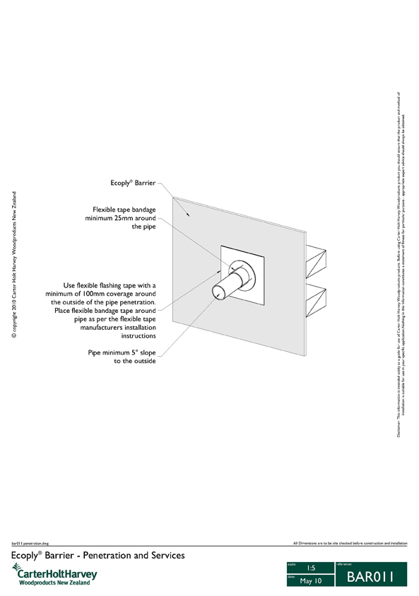
Fire stopping basics
Shows basic concept of sealing penetrations where fire/acoustic separation is specified.
This guide sketch belongs in the fire-stopping card because it clearly shows a rated wall/floor, service penetration, annular gap, fire sealant, backing and evidence label. Fire-stopping is uncommon in ordinary standalone houses unless a rated separation is specified; use only the tested system named in the project documents.
Technical parts to learn
Rated wall/floor: Learn the term, then confirm exact shape, size, product, laps, clearances, fixings, or tolerances from the project detail.
Penetration: Learn the term, then confirm exact shape, size, product, laps, clearances, fixings, or tolerances from the project detail.
Sealant/system: Learn the term, then confirm exact shape, size, product, laps, clearances, fixings, or tolerances from the project detail.
Label: Learn the term, then confirm exact shape, size, product, laps, clearances, fixings, or tolerances from the project detail.
Inspection evidence: Learn the term, then confirm exact shape, size, product, laps, clearances, fixings, or tolerances from the project detail.
Not proven by this image
Rated wall/floor requirement
Penetration type
Approved tested system
Sealant/backing depth
Installer evidence/label
Hidden dimensions, laps, clearances, fixings, cover, tolerances, and product-specific requirements must be checked in the consented drawings, engineer details, manufacturer instructions, and inspection records.
What the CM checks
Use only specified tested systems
Check consented fire/acoustic requirements
Photograph labels
Common defects
Wrong product
Unsealed penetration
No evidence
How to use this image
The photo annotations now describe visible image features only. Replace with the actual consented detail, engineer detail, manufacturer detail, or a marked-up site photo before using on a live project.
Use MBIE Building Performance to find the current Building Code clauses, Acceptable Solutions, Verification Methods, updates, and technical guidance.
Manufacturer specification
Use the exact current installation manual, warranty requirements, BRANZ/Appraisal information where applicable, and product data sheet for the product on site.
Consented drawings and specifications
The issued consent drawings, stamped specifications, engineering drawings, RFIs, minor variations, and amendments control the specific project.
Insufficient data to verify
Insufficient data to verify — check the consented drawings, project specification, relevant NZ Standard, or council requirement.
Closeout
Final handover flow
Shows the flow from final QA through defects, CCC evidence, handover, and DLP.
This flow image belongs in the final handover card because it is a process diagram, not a construction detail. It shows the closeout sequence from final QA through CCC evidence, handover and DLP.
Technical parts to learn
Final QA: Learn the term, then confirm exact shape, size, product, laps, clearances, fixings, or tolerances from the project detail.
Defects: Learn the term, then confirm exact shape, size, product, laps, clearances, fixings, or tolerances from the project detail.
Certificates: Learn the term, then confirm exact shape, size, product, laps, clearances, fixings, or tolerances from the project detail.
CCC: Learn the term, then confirm exact shape, size, product, laps, clearances, fixings, or tolerances from the project detail.
Keys/manuals: Learn the term, then confirm exact shape, size, product, laps, clearances, fixings, or tolerances from the project detail.
DLP log: Learn the term, then confirm exact shape, size, product, laps, clearances, fixings, or tolerances from the project detail.
Not proven by this image
Final QA status
Defects register
Certificates/PS3/PS4/LBP records
CCC evidence
O&M manuals and warranties
Hidden dimensions, laps, clearances, fixings, cover, tolerances, and product-specific requirements must be checked in the consented drawings, engineer details, manufacturer instructions, and inspection records.
What the CM checks
Track documents early
Close defects with evidence
Explain maintenance to client
Common defects
Missing certificate
Unclear defect owner
Poor client handover
How to use this image
The photo annotations now describe visible image features only. Replace with the actual consented detail, engineer detail, manufacturer detail, or a marked-up site photo before using on a live project.
MBIE guidance explains that work should be built to the issued building consent, inspections must be managed, and records/certificates should be kept for CCC.
Auckland Council explains local building consent processes, CCC, related certificates, producer statements, LBP notification, and whether resource consent may also be needed.
Consented drawings and specifications
The issued consent drawings, stamped specifications, engineering drawings, RFIs, minor variations, and amendments control the specific project.
Insufficient data to verify
Insufficient data to verify — check the consented drawings, project specification, relevant NZ Standard, or council requirement.